
Bekannt aus

PREMIUM CBD
Seit einiger Zeit zeigt sich glücklicherweise wieder ein erhöhtes Maß an Akzeptanz gegenüber der Hanfpflanze und Cannabisprodukten, und da wir uns in der Verpflichtung sehen, haben wir beschlossen, nicht blind einem Turbokapitalismus hinterherzulaufen, sondern eigene, ökologisch wie ökonomisch sanftere Wege zu beschreiten.


Die wichtigsten Infos rund um unser CBD
Was ist eigentlich der Unterschied zwischen Hanföl und CBD-Öl? Was sind Cannabinoide? In unseren informativen Blog-Artikeln gibt es die Antworten auf all diese Fragen und viele praktische Alltagstipps! Du suchst nach genauen Informationen zu unseren Produkten? Die findest du im Online-Shop!


Unser Ratgeber: Wissenswertes rund um Cannabis und seine Inhaltsstoffe
Premium-CBD von Dr. Greenthumb
Hanf ist eine der ältesten kultivierten Nutzpflanzen, die seit Jahrtausenden auf vielfältige Weise eingesetzt wird und ein unglaubliches Potenzial besitzt. Aus dem Rohstoff Hanf werden zum Beispiel Kleidung, Papier, Seile, Körperpflegeprodukte, Lebensmittel und Baustoffe hergestellt. Wir von Dr. Greenthumb sind ein österreichisches Unternehmen und haben es uns zur Aufgabe gemacht, hochwertige Hanfprodukte zu vertreiben und unseren Kunden die positiven Eigenschaften der Hanfpflanze zugänglich zu machen. Dabei achten wir besonders auf eine nachhaltige und sanfte Herstellung und einen fairen Vertrieb. Neben unserer unternehmerischen Tätigkeit setzen wir uns auch für die Liberalisierung von Cannabis in Europa ein, da es unser Anliegen ist, den Zugang zu dieser besonderen Nutzpflanze zu erleichtern.
In unserem Online-Shop findest du eine ständig wechselnde Auswahl an verschiedenen Hanfprodukten, die sich immer an den Bedürfnissen unserer Kunden orientiert. Unsere CBD-Produkte sind z. B. in Form von getrockneten Hanfblüten oder als hochwertiges CBD-Öl erhältlich. In unserem Online-Shop findest du detaillierte Informationen zu jedem unserer Produkte. Bei weiteren Fragen steht dir unser kompetentes Team jederzeit mit Rat und Tat zur Seite. Kontaktiere uns ganz einfach telefonisch unter +43 (0) 660 4201 420 oder schreib uns eine E-Mail an office@dr-greenthumb.at.
Nachhaltigkeit: geprüftes Bio-CBD
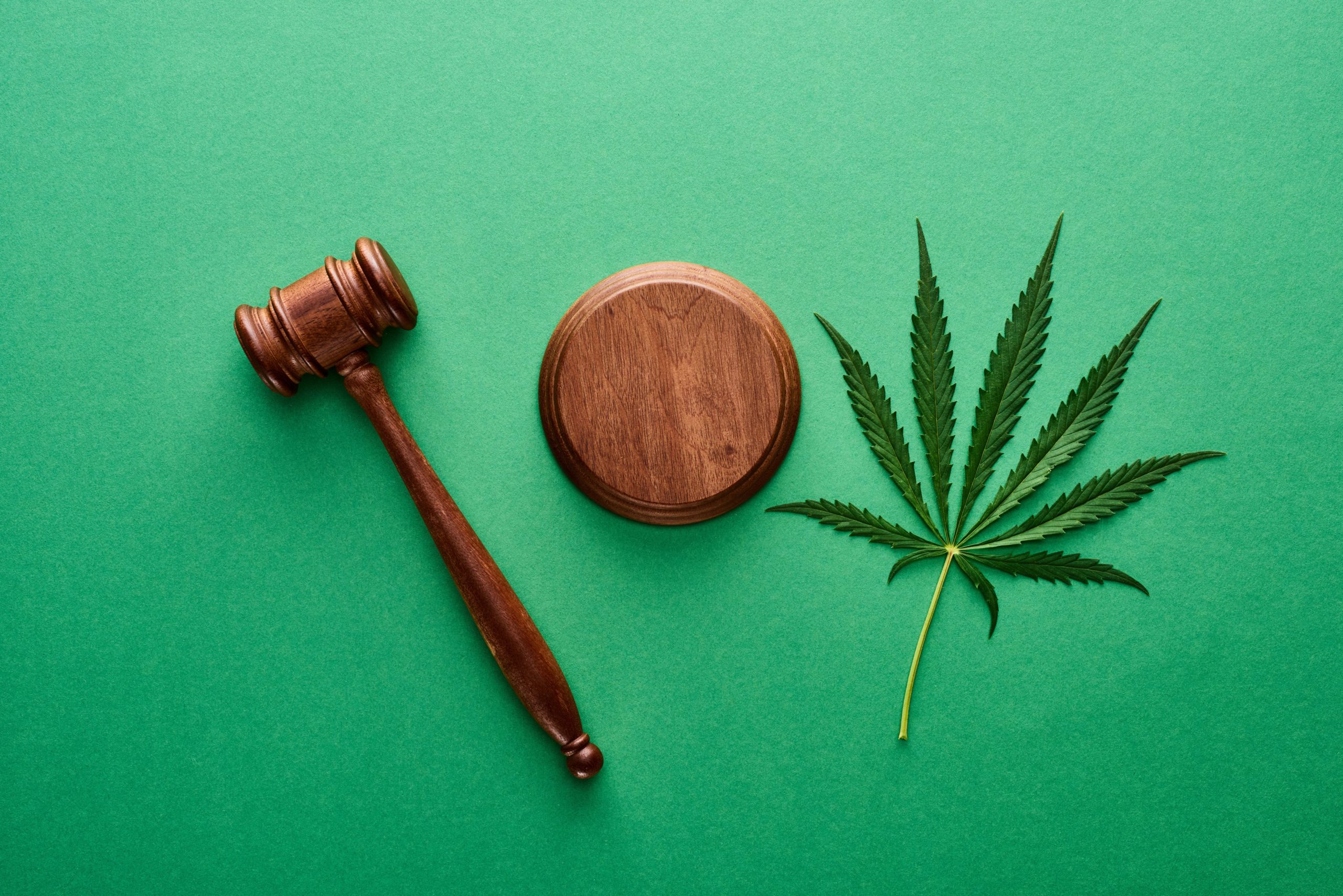
Die hohe Qualität unserer Hanfprodukte hat bei Dr. Greenthumb absolute Priorität und wird streng kontrolliert. Unsere hochwertigen CBD-Blüten stammen ausschließlich von biologischen Hanfpflanzen, die in Österreich professionell kultiviert und handverlesen werden und in einer GAP- und BIO-zertifizierten Produktion entstehen. Im Gegensatz zum THC handelt es sich beim CBD um einen Bestandteil der Hanfpflanze, der keine psychoaktive bzw. berauschende Wirkung besitzt und daher nicht als Suchtmittel eingestuft wird. Auf den Hanfprodukten von Dr. Greenthumb ist sowohl der CBD- als auch der THC-Anteil vermerkt und alle unsere Produkte sind selbstverständlich im EU-Sortenkatalog zertifiziert.
CBD Fruchtgummis
Bei uns findest du auch eine süße Versuchung mit unseren CBD Fruchtgummis. Wir wissen von der positiven Wirkung des CBD bestens bescheid und wollen auch dir in form von Süßigkeiten den Geschmack und Mehrwert dieses Canabinoids bieten. Sie sind die perfekte alternative zu unseren CBD Ölen und zeichnen sich durch ihren, fruchtigen und leckeren Geschmack aus und entfalten trotzdem die volle Wirkung des hochwertigen CBD Wirkstoff. In unserem Shop findest du nur die beste Auswahl 🙂